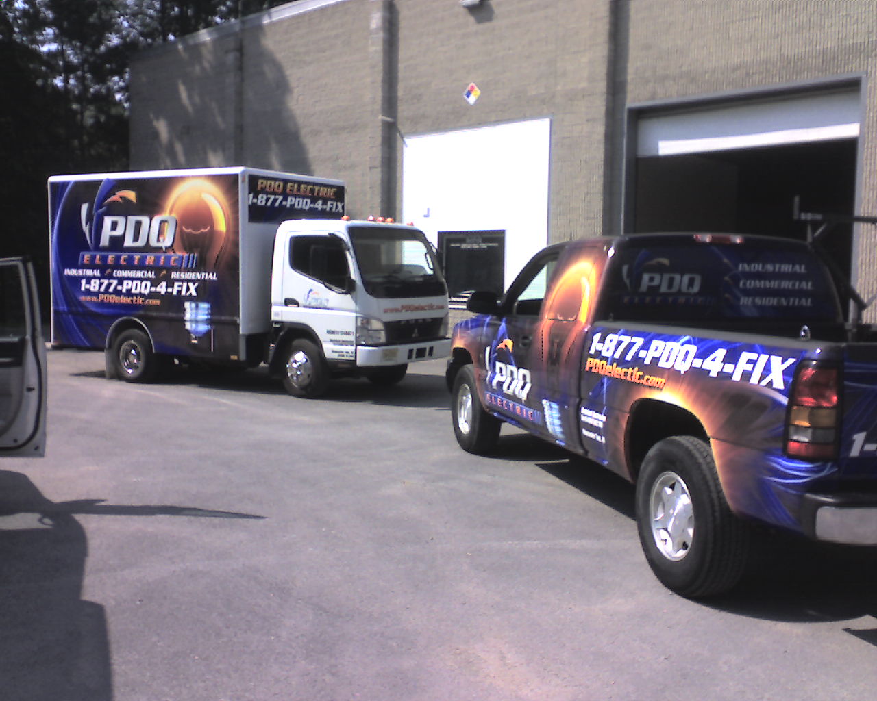
PDQIE Service Vehicles   Industrial - Commercial  PDQ Industrial Electric  Electrical Contractor   Reddy Kilowatt

PDQ Electric Corp

NJ, PA, DE, MD, NY, CT, DC, MA, RI


HOME SERVICE AREA QUOTE REQUEST EMERGENCY 24-7 CONTACT PDQIE SITE MAP


PDQIE Panel Room

PDQIE - PDQ Industrial Electric

Grounding and Bonding Systems Outline


 Fault Lightning Signal
 
GROUNDED VERSUS GROUNDING
  • Grounded vs. grounding in an electrical system. Grounded system refers to a system where a conductor is grounded and is intended to or may carry current in the normal operation. The neutral on a wyesystem is a prime example of a grounded conductor.
  • The grounding conductor system is not intended to carry operational current in its design. This path is intended to carry unwanted and fault currents for protection.

TYPES OF AC GROUNDED SYSTEMS

  • Ungrounded system
  • Solidly Grounded System
  • Resistance Grounded
  • Reactance Grounded
  • Ground Fault Neutralizer

WHICH SYSTEM TO USE??

  • Safety -Who is Operating the System
  • Ground Fault Detection
  • Signal Reference
  • Touch Potential (also static)
  • Available Fault Currents?
  • Operation Stability
  • System Response

UNGROUNDED SYSTEM

  • Type of system typically used on is a Delta service.
  • Some time used on a floating Wye
  • Detection System in Place
    • Ground Detection by Lighting
    • Zigzag Grounding Transformer
    • Ground Relay
    • Ground Fault ???

DETECTION DEVICES

SOLIDLY GROUNDED SYSTEM

  • Usually use in WyeSystems
  • Return Fault current to trip overcurrentprotection device quickly
  • Usually better reference and safer system
  • Much better for lightning protection
  • Can be used in Corner Grounded Delta
    • Problems with phase grounded re-grounded
    • Not good on lightning protection equipment

RESISTIVE GROUNDED

  • Low Resistance
    • Limit Fault Current
    • Minimizes the damage at the fault
    • Used usually with multiple sources i.e. transformers, and or generators
  • High Resistance
    • Enables system operation with one phase grounded
    • Enables current to flow for detection networks
    • Current is low enough so that no damage occurs

REACTANCE GROUNDING

  • Reactor connected between system neutral and ground
    • Reduces the ground fault current between phase and ground
    • Usually higher fault current than low resistance grounding
    • Better coordination with fault currents on multi-grounded system. Mostly used on system above 5kV.

GROUND-FAULT NEUTALIZER

  • Reactor with relatively high value of reactance.
  • Usually on system above 15kV phase to ground air exposed. (overhead Transmission and Distribution)
  • May provide insulator flashover with self-extinguishing characteristics.

SEPARATELY DERIVED SYSTEM

  • The system grounding conductor for a separately derived system shall be grounded at only one point.
  • Main system Disconnecting means for a main utility feed, or a step down or step up transformer, or a generator could all be separately derived systems.
  • When grounded it will be grounded at the nearest grounding electrode.

GROUNDING ELECTRODE SYSTEM and
GROUNDING ELECTRODE CONDUCTOR

  • NEC 250.50 (Grounding Electrode System) 250.52 Electrodes
    • Water Pipe if 10 ft. or more of metal water pipe is in contact with the earth.
    • Metal Frame of the Building or Structure
    • Concrete-Encased Electrode in at least 2” of concrete located within and near the bottom of a concrete foundation or footing that is in indirect contact with the earth.
    • Ground Ring encircling the building or structure in direct contact with the earth
    • Rod or Pipe electrode not less than 8 ft in length
    • Plate Electrode not less than 2 square ft.
    • Other Local underground systems such as piping, underground tanks and underground metal well casing
    • NOT Permitted
      • Metal underground gas piping
      • Aluminum electrode

Grounding Diagram

GROUNDING ELECTRODE SYSTEM

  • Installation NEC 250.53
    • This requirement clarifies that the supplemental electrode system must be installed as if it were the sole grounding electrode
  • Bonding NEC 250.53 C
    • This requirement is for bonding of multiple electrodes.

BONDING

  • Bonding for
    • Main Bonding Jumper
    • System Bonding Jumper
    • Electrode Bonding
    • Bonding
      • Where necessary to ensure electrical continuity and the capacity to conduct safely and fault current likely imposed.