 Industrial - Commercial
  Electrical
Contractor
PDQ Electric Corp
NJ, PA, DE, MD, NY, CT, DC, MA, RI
|

PDQIE - PDQ Industrial ElectricFiber Optic Systems (Telcom & Non-Telecom)Fiber Optics Telecom
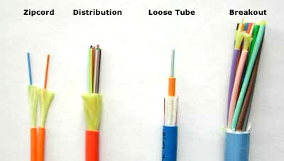
Bending Sensitivity in Fiber Bulk Cable and Cable AssembliesFiber optic technology is a revolution in connectivity. Using the power of light, signals are sent at blinding speeds for huge distances without need of Repeating or Amplification. However, one of the biggest drawbacks of fiber optic cabling was that the glass core is sensitive to being bent at sharp angles or being flexed frequently. Now Bend Insensitive (BI) Fiber Optic Bulk Cable and Cable Assemblies are a solution and are specifically designed to eliminate the sensitivity to bending that makes using fiber optic cabling prohibitive in so many situations. Now fiber cables can be used in Contact Centers, Robotics, Tight Wiring Closets and so many more places. Bend Insensitive Fiber Cable offers greater flexibility in demanding environments, than traditional fiber cable. It is typically used in Data Centers or any space constrained area where tight bends and flexibility are required. Available in singlemode simplex, duplex, and 6 & 12 count breakout options. Simplex and Zip Cord: Simplex cables are one fiber, tight-buffered (coated with a 900 micron buffer over the primary buffer coating) with Kevlar (aramid fiber) strength members and jacketed for indoor use. The jacket is usually 3mm (1/8 in.) diameter. Zipcord is simply two of these joined with a thin web. It's used mostly for patch cord and backplane applications, but zipcord can also be used for desktop connections. Distribution Cables: They contain several tight-buffered fibers bundled under the same jacket with Kevlar strength members and sometimes fiberglass rod reinforcement to stiffen the cable and prevent kinking. These cables are small in size, and used for short, dry conduit runs, riser and plenum applications. The fibers are double buffered and can be directly terminated, but because their fibers are not individually reinforced, these cables need to be broken out with a "breakout box" or terminated inside a patch panel or junction box. Loose Tube Cables: These cables are composed of several fibers together inside a small plastic tube, which are in turn wound around a central strength member and jacketed, providing a small, high fiber count cable. This type of cable is ideal for outside plant trunking applications, as it can be made with the loose tubes filled with gel or water absorbent powder to prevent harm to the fibers from water. It can be used in conduits, strung overhead or buried directly into the ground. Since the fibers have only a thin buffer coating, they must be carefully handled and protected to prevent damage. Breakout Cables: They are made of several simplex cables bundled together. This is a strong, rugged design, but is larger and more expensive than the distribution cables. It is suitable for conduit runs, riser and plenum applications. Because each fiber is individually reinforced, this design allows for quick termination to connectors and does not require patch panels or boxes. Breakout cable can be more economic where fiber count isn't too large and distances too long, because is requires so much less labor to terminate. Fiber-optic communication is a method of transmitting information from one place to another by sending pulses of light through an optical fiber. The light forms an electromagnetic carrier wave that is modulated to carry information. First developed in the 1970s, fiber-optic communication systems have revolutionized the telecommunications industry and have played a major role in the advent of the Information Age. Because of its advantages over electrical transmission, optical fibers have largely replaced copper wire communications in core networks in the developed world. The process of communicating using fiber-optics involves the following basic steps: Creating the optical signal involving the use of a transmitter, relaying the signal along the fiber, ensuring that the signal does not become too distorted or weak, receiving the optical signal, and converting it into an electrical signal. Optical fiber is used by many telecommunications companies to transmit telephone signals, Internet communication, and cable television signals. Due to much lower attenuation and interference, optical fiber has large advantages over existing copper wire in long-distance and high-demand applications. However, infrastructure development within cities was relatively difficult and time-consuming, and fiber-optic systems were complex and expensive to install and operate. Due to these difficulties, fiber-optic communication systems have primarily been installed in long-distance applications, where they can be used to their full transmission capacity, offsetting the increased cost. Modern fiber-optic communication systems generally include an optical transmitter to convert an electrical signal into an optical signal to send into the optical fiber, a cable containing bundles of multiple optical fibers that is routed through underground conduits and buildings, multiple kinds of amplifiers, and an optical receiver to recover the signal as an electrical signal. The information transmitted is typically digital information generated by computers, telephone systems, and cable television companies. TRANSMITTERS In its simplest form, an LED is a forward-biased p-n junction, emitting light through spontaneous emission, a phenomenon referred to as electroluminescence. The emitted light is incoherent with a relatively wide spectral width of 30-60 nm. LED light transmission is also inefficient, with only about 1 % of input power, or about 100 microwatts, eventually converted into launched power which has been coupled into the optical fiber. However, due to their relatively simple design, LEDs are very useful for low-cost applications. Communications LEDs are most commonly made from gallium arsenide phosphide (GaAsP) or gallium arsenide (GaAs). Because GaAsP LEDs operate at a longer wavelength than GaAs LEDs (1.3 micrometers vs. 0.81-0.87 micrometers), their output spectrum is wider by a factor of about 1.7. The large spectrum width of LEDs causes higher fiber dispersion, considerably limiting their bit rate-distance product (a common measure of usefulness). LEDs are suitable primarily for local-area-network applications with bit rates of 10-100 Mbit/s and transmission distances of a few kilometers. LEDs have also been developed that use several quantum wells to emit light at different wavelengths over a broad spectrum, and are currently in use for local-area WDM networks. A semiconductor laser emits light through stimulated emission rather than spontaneous emission, which results in high output power (~100 mW) as well as other benefits related to the nature of coherent light. The output of a laser is relatively directional, allowing high coupling efficiency (~50 %) into single-mode fiber. The narrow spectral width also allows for high bit rates since it reduces the effect of chromatic dispersion. Furthermore, semiconductor lasers can be modulated directly at high frequencies because of short recombination time. Laser diodes are often directly modulated, that is the light output is controlled by a current applied directly to the device. For very high data rates or very long distance links, a laser source may be operated continuous wave, and the light modulated by an external device such as an electro-absorption modulator or Mach-Zehnder interferometer. External modulation increases the achievable link distance by eliminating laser chirp, which broadens the linewidth of directly-modulated lasers, increasing the chromatic dispersion in the fiber. RECEIVERS Optical-electrical converters are typically coupled with a transimpedance amplifier and a limiting amplifier to produce a digital signal in the electrical domain from the incoming optical signal, which may be attenuated and distorted while passing through the channel. Further signal processing such as clock recovery from data (CDR) performed by a phase-locked loop may also be applied before the data is passed on. FIBER Two main types of optical fiber used in optic communications include multi-mode optical fibers and single-mode optical fibers. A multi-mode optical fiber has a larger core (= 50 micrometres), allowing less precise, cheaper transmitters and receivers to connect to it as well as cheaper connectors. However, a multi-mode fiber introduces multimode distortion, which often limits the bandwidth and length of the link. Furthermore, because of its higher dopant content, multi-mode fibers are usually expensive and exhibit higher attenuation. The core of a single-mode fiber is smaller (<10 micrometres) and requires more expensive components and interconnection methods, but allows much longer, higher-performance links. In order to package fiber into a commercially-viable product, it is typically protectively-coated by using ultraviolet (UV), light-cured acrylate polymers, then terminated with optical fiber connectors, and finally assembled into a cable. After that, it can be laid in the ground and then run through the walls of a building and deployed aerially in a manner similar to copper cables. These fibers require less maintenance than common twisted pair wires, once they are deployed. AMPLIFIERS An alternative approach is to use an optical amplifier, which amplifies the optical signal directly without having to convert the signal into the electrical domain. It is made by doping a length of fiber with the rare-earth mineral erbium, and pumping it with light from a laser with a shorter wavelength than the communications signal (typically 980 nm). Amplifiers have largely replaced repeaters in new installations. WAVELENGTH-DIVISION MULTIPLEXING BANDWITH-DISTANCE PRODUCT Through a combination of advances in dispersion management, wavelength-division multiplexing, and optical amplifiers, modern-day optical fibers can carry information at around 14 Terabits per second over 160 kilometers of fiber. Engineers are always looking at current limitations in order to improve fiber-optic communication, and several of these restrictions are currently being researched. For instance, NTT was able to achieve 69.1 Tbit/s transmission by applying wavelength division multiplex (WDM) of 432 wavelengths with a capacity of 171 Gbit/s over a single 240 km-long optical fiber on March 25, 2010. This has been the highest optical transmission speed ever recorded. The per-channel light signals propagating in the fiber have been modulated at rates as high as 111 gigabits per second by NTT, although 10 or 40 Gbit/s is typical in deployed systems. Each fiber can carry many independent channels, each using a different wavelength of light (wavelength-division multiplexing (WDM)). The net data rate (data rate without overhead bytes) per fiber is the per-channel data rate reduced by the FEC overhead, multiplied by the number of channels (usually up to eighty in commercial dense WDM systems as of 2008). The current laboratory fiber optic data rate record, held by Bell Labs in Villarceaux, France, is multiplexing 155 channels, each carrying 100 Gbit/s over a 7000 km fiber. DISPERSION In single-mode fiber performance is primarily limited by chromatic dispersion (also called group velocity dispersion), which occurs because the index of the glass varies slightly depending on the wavelength of the light, and light from real optical transmitters necessarily has nonzero spectral width (due to modulation). Polarization mode dispersion, another source of limitation, occurs because although the single-mode fiber can sustain only one transverse mode, it can carry this mode with two different polarizations, and slight imperfections or distortions in a fiber can alter the propagation velocities for the two polarizations. This phenomenon is called fiber birefringence and can be counteracted by polarization-maintaining optical fiber. Dispersion limits the bandwidth of the fiber because the spreading optical pulse limits the rate that pulses can follow one another on the fiber and still be distinguishable at the receiver. Some dispersion, notably chromatic dispersion, can be removed by a 'dispersion compensator'. This works by using a specially prepared length of fiber that has the opposite dispersion to that induced by the transmission fiber, and this sharpens the pulse so that it can be correctly decoded by the electronics. ATTENUATION
Note that this table shows that current technology has managed to bridge the second and third windows that were originally disjoint. Historically, there was a window used below the O band, called the first window, at 800-900 nm; however, losses are high in this region so this window is used primarily for short-distance communications. The current lower windows (O and E) around 1300 nm have much lower losses. This region has zero dispersion. The middle windows (S and C) around 1500 nm are the most widely used. This region has the lowest attenuation losses and achieves the longest range. It does have some dispersion, so dispersion compensator devices are used to remove this. REGENERATION Recent advances in fiber and optical communications technology have reduced signal degradation so far that regeneration of the optical signal is only needed over distances of hundreds of kilometers. This has greatly reduced the cost of optical networking, particularly over undersea spans where the cost and reliability of repeaters is one of the key factors determining the performance of the whole cable system. The main advances contributing to these performance improvements are dispersion management, which seeks to balance the effects of dispersion against non-linearity; and solitons, which use nonlinear effects in the fiber to enable dispersion-free propagation over long distances. LAST MILE In the US, Verizon Communications provides a FTTH service called FiOS to select high-ARPU (Average Revenue Per User) markets within its existing territory. The other major surving ILEC (or Incumbent Local Exchange Carrier), AT&T, uses a FTTN (Fiber To The Node) service called U-verse with twisted-pair to the home. Their MSO competitors employ FTTN with coax using HFC. All of the major access networks use fiber for the bulk of the distance from the service provider's network to the customer. The globally dominant access network technology is EPON (Ethernet Passive Optical Network). In Europe, and among telcos in the United States, BPON (ATM-based Broadband PON) and GPON (Gigabit PON) are favored because of their roots in the FSAN (Full Service Access Network) and ITU-T standards organizations under their control. Comparison with electrical transmission: The choice between optical fiber and electrical (or copper) transmission for a particular system is made based on a number of trade-offs. Optical fiber is generally chosen for systems requiring higher bandwidth or spanning longer distances than electrical cabling can accommodate. The main benefits of fiber are its exceptionally low loss (allowing long distances between amplifiers/repeaters), its absence of ground currents and other parasite signal and power issues common to long parallel electric conductor runs (due to its reliance on light rather than electricity for transmission, and the dielectric nature of fiber optic), and its inherently high data-carrying capacity. Thousands of electrical links would be required to replace a single high bandwidth fiber cable. Another benefit of fibers is that even when run alongside each other for long distances, fiber cables experience effectively no crosstalk, in contrast to some types of electrical transmission lines. Fiber can be installed in areas with high electromagnetic interference (EMI), such as alongside utility lines, power lines, and railroad tracks. Nonmetallic all-dielectric cables are also ideal for areas of high lightning-strike incidence. For comparison, while single-line, voice-grade copper systems longer than a couple of kilometers require in-line signal repeaters for satisfactory performance; it is not unusual for optical systems to go over 100 kilometers (60 miles), with no active or passive processing. Single-mode fiber cables are commonly available in 12 km lengths, minimizing the number of splices required over a long cable run. Multi-mode fiber is available in lengths up to 4 km, although industrial standards only mandate 2 km unbroken runs. In short distance and relatively low bandwidth applications, electrical transmission is often preferred because of its
Optical fibers are more difficult and expensive to splice than electrical conductors. And at higher powers, optical fibers are susceptible to fiber fuse, resulting in catastrophic destruction of the fiber core and damage to transmission components. Because of these benefits of electrical transmission, optical communication is not common in short box-to-box, backplane, or chip-to-chip applications; however, optical systems on those scales have been demonstrated in the laboratory. In certain situations fiber may be used even for short distance or low bandwidth applications, due to other important features:
Optical fiber cables can be installed in buildings with the same equipment that is used to install copper and coaxial cables, with some modifications due to the small size and limited pull tension and bend radius of optical cables. Optical cables can typically be installed in duct systems in spans of 6000 meters or more depending on the duct's condition, layout of the duct system, and installation technique. Longer cables can be coiled at an intermediate point and pulled farther into the duct system as necessary. Fiber Optics Non-TelecomOptic fiber is used for more than telecommunications. It is also used to deliver light from sources and to detectors in dozens of industries and applications. Fibers can go where light bulbs and detectors won’t. They can shape light in ways that no other technique can. Fibers can route light where lenses and mirrors can’t. Other types of light guides can be fabricated from materials like sheets, tubes, and rods. To help potential users to visualize fiber applications and specify fiber use, listed below is a summary of many of the places where fibers are currently used.
| ||||||||||||||||||||||||
(877) 737-4349 (Toll Free)
(877) PDQ-4-FIX (Toll
Free)
(856) 625-6969 (Text
Messaging)
PDQ ia an Acronym for "Pretty Damn Quick"
|
PDQIE, www.PDQIE.com, info@PDQIE.com, quote@PDQIE.com, Ryan@PDQIE.com, PDQ Industrial Electric, www.PDQIndustrialElectric.com, info@PDQIndustrialElectric.com, quote@PDQIndustrialElectric.com, Ryan@PDQIndustrialElectric.com are marketing tools of PDQ Electric Corp, a NJ Licensed Electrical Contractor. Reddy Kilowatt® is a Registered Trademark of Northern States Power Company. The information on this website is believed to be reliable, but we cannot guarantee that information will be accurate, complete and current at all times and should be reaffirmed by a licensed professional before relying on it. PDQIE will from time to time revise information, products and services described in-on this Website, and reserves the right to make such changes without notice. Use of this Website is entirely at your risk. Materials and information in this Website (including text, graphics, and functionality) are presented without express or implied warranties of any kind and are provided "as is". It is your responsibility to evaluate the accuracy, completeness and usefulness of any opinions, advice, services and information provided.
